
Overview
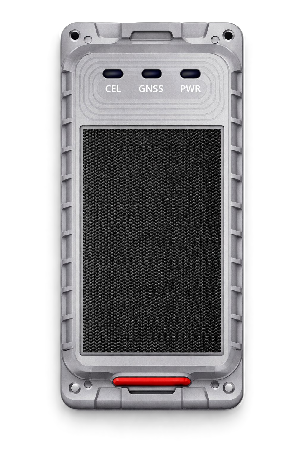
The GL601MG is a rugged, solar-powered asset tracker designed for monitoring trailers, containers, and other non-powered equipment. It features an IP67-rated waterproof and dustproof design, making it suitable for long-term outdoor use in harsh environments.
Note: With integrated solar charging, the device can operate for up to ~6 years with minimal maintenance. |
In addition to location tracking, the device also includes a light sensor for tamper detection and a temperature sensor for environmental monitoring. The device supports reliable connectivity using modern cellular networks and can be extended with BLE and Wi-Fi capabilities for additional use cases.
To optimize performance, the device:
- Reports more frequently when the asset is moving
- Reduces reporting when the asset is stationary to conserve battery
What's in the Box?
Verify that the following items are included before installation:
Standard Items
GL601MG Tracker Unit |
|
GL601 Series Data Cable |
|
Self-tapping mounting screws (x4) |
|
Light Sensor Foam |
|


Optional Accessories
Steel Cable and Steel Plates |
|
Magnetic Buckle Kit |
|


Terms and Abbreviations
Abbreviation | Description |
RXD | Receive Data |
TXD | Transmit Data |
VIN | VBUS-5V |
GND | Ground |
Device Overview
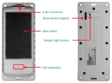
The diagram below shows the key components on the front (top) and back of the GL601MG.
1. Solar Panel (Top Side)
- The solar panel helps recharge the internal battery using sunlight.
- For best performance, this side of the device should always face upward and remain unobstructed.
2. Three LED Indicators
These LEDs help confirm that the device is powered on and functioning correctly during installation.
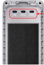
LED | Color | Event | State |
CELL LED | Green | Searching network | Fast flashing |
CELL LED | Green | The device has been registered to network | Slow flashing |
CELL LED | Green | SIM is locked by PIN or abnormal | Solid ON |
CELL LED | Green | Modem OFF | Solid OFF |
GNSS LED | Blue | GPS is in the process of fixing | Fast flashing |
GNSS LED | Blue | GPS chipset is abnormal | Slow flashing |
GNSS LED | Blue | GPS is on and GPS gets fix | Solid ON |
GNSS LED | Blue | GPS OFF | Solid OFF |
POWER LED | Red | Battery power is low | Fast flashing |
POWER LED | Red | Charging | Slow flashing |
POWER LED | Red | Charge complete | Solid ON |
POWER LED | Red | No charging | Solid OFF |
Flashing definitions:
- Fast flashing: 100ms on / 200ms off
- Slow flashing: 200ms on / 1800ms off
3. 4-Pin Magnetic Connector
- The GL601MG device has a 4-pin magnetic connector on the side.
- This connector is used only when connecting the GL601 Series Data Cable for configuration, firmware updates, or charging.
Connector location:
- Located on the side of the device
- Protected by the device casing
- Designed for magnetic snap-on connection for easy attachment of the GL601 Series Data Cable
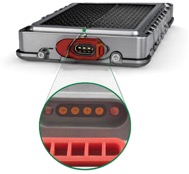
Pin functions:
PIN No. | PIN Name | Function Description |
1 | VBUS | USB PWR (USB Power Input) |
2 | GND | GND (Ground) |
3 | UART_RXD | Debug Receive Data |
4 | UART_TXD | Debug Transmit Data |
4. Magnetic Reed Switch (Power Control)
The reed switch allows the device to be powered on using a magnet. A magnet swipe across this area activates the device when the battery switch is set to ON.
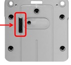
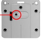
5. Tamper Light Sensor
This sensor detects exposure to light when the device casing is opened or removed. It helps identify potential tampering events.
Charging the Device (Important)
Before installing the device, it is strongly recommended to fully charge the device.
Charging Steps
- Locate the 4-pin magnetic connector on the device.
- Carefully align and attach the USB charging cable to the device connector.
- Allow the magnets to guide the connection. The cable will snap into place automatically when aligned correctly. If the cable does not attach, rotate or reposition it until the magnets align and the connector attaches smoothly.
- Plug the cable into a standard USB power source (such as a wall adapter or USB port).
- Charge the device for approximately 3–4 hours to reach a full charge.
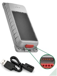
Important: Magnetic attraction indicates that the cable is properly aligned and securely connected. Do not force the connection. Keep the connector clean and free from oil, dust, and moisture. The charging cable is for charging only and is not required after installation. Remove the cable and close the port cover tightly after charging. |
Pre-Installation Guidelines
Before installing the device:
- Ensure the device is fully charged (recommended).
- Confirm adequate cellular network coverage in the installation area.
- Select a stable and secure mounting surface.
- Choose a mounting location where the solar panel can face the sky for optimal charging and better signal reception.
Avoid:
- Installing the device under metal surfaces.
- Installing the device in enclosed environments where GPS and network signals may be weak.
Installation of Asset Tracker GL601MG
Follow these steps for proper installation: activate the device, select a mounting location, and mount the device.
Step 1 – Activate the Device
To install the asset tracker on the vehicle, first activate the device by following these steps:
To activate the device:
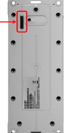
- Locate the magnet attached to the back of the device.
- Remove the magnet from the device.
Once the magnet is removed:
- The device exits sleep mode and powers on automatically.
- LED indicators turn on to show device status.
- The device begins normal operation.
Step 2 – Select Mounting Location
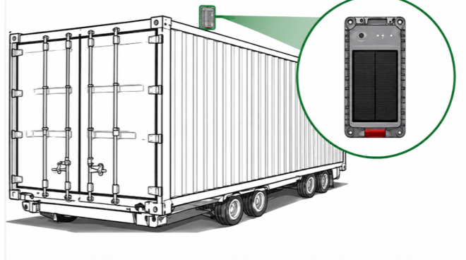
- Choose a flat, open surface to ensure stable and secure mounting.
- Ensure clear sky visibility for reliable GPS signal and accurate tracking.
- Prefer locations with good network coverage to maintain consistent data transmission.
- Select a placement that reduces the risk of tampering or unauthorized access.
Step 3 – Mount Using Screw (Recommended)
Mounting the device using screws provides the most secure and reliable installation, especially for long-term deployments.
- Position the device on a stable and secure mounting surface.
- Ensure the solar panel is facing upward for optimal charging.
- Secure the device using the provided self-tapping screws.
- Tighten all screws properly to ensure the device remains firmly in place and does not shift, fall off, or get damaged.
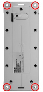
Note: The provided self-tapping screws are suitable for most metal surfaces. For other surface types, use appropriate mounting hardware if required. |
Step 4 – Mount Using Magnetic Buckle (Optional)
If installing the device using the magnetic buckle kit:
- Ensure the device is powered ON before installation.
- Attach the magnetic buckle to mount the device on the surface.
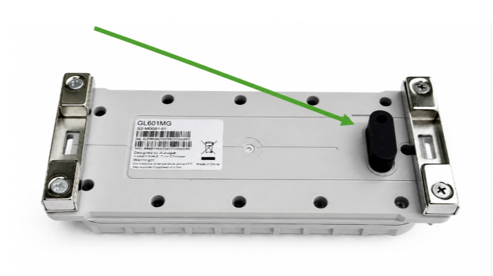
Note: The magnetic buckle contains magnets that may interfere with the device’s reed switch. Always power on the device before installing the magnetic buckle to prevent unintended power-on behavior. |
Tamper Sensor Installation (Foam Usage)
The light sensor foam prevents unwanted light from reaching the tamper sensor, especially when the device is installed on uneven surfaces, helping avoid false tamper alerts. Use the foam when installing on surfaces that are uneven, curved, rough, or not fully flat.
- Place the light sensor foam over the tamper sensor area on the underside of the device.
- Position the device on the mounting surface (use foam only if the surface is uneven or has gaps).
- Secure the device using self-tapping screws while ensuring the foam compresses evenly.
- Tighten the device firmly so the foam fills all gaps and blocks any light entry.
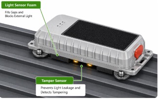
Important: The foam is optional and should be used only when needed to prevent false tamper alerts caused by light leakage. It is not required for flat, well-sealed surfaces. |
Installation Verification
After installation, verify that the device is powered on, connected, and reporting correctly.
- Confirm the device powers on and LED indicators show normal operation.
- Verify the device is registered on the cellular network.
- Ensure the device has acquired a GPS signal (location fix).
- Check that the device is visible on the Azuga platform and reporting location data.
Powering Off the Device (If Required)
If the device needs to be powered off:
- Locate the 11 screws on the back side of the device.
- Use a screwdriver (recommended torque: 7.0 ± 0.5 kgf·cm²) to remove all screws.
- Carefully open the device casing.
- Locate the battery switch inside the device.
- Toggle the battery switch to the OFF position.
- Reinstall the device casing.
- Reinsert all 11 screws.
- Tighten the screws to 7 kgf·cm² torque.
The device will then power off.
Important: Tighten the screws in a diagonal sequence to ensure even sealing. This helps maintain waterproof protection and prevents damage to the screw heads. |
Setting Up and Managing Assets in Azuga Fleet
The Azuga Fleet web application allows you to set up, track, and manage your assets. To begin tracking, you must assign the tracking devices to their respective assets. Follow the steps below:
Step 1: Prepare Asset Details
Note down the serial number of the asset tracker device. Identify which asset the device will be installed on, and assign a friendly name (for example, Generator). Please keep these asset names short.
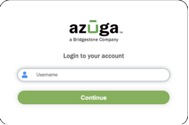
Step 2: Log In to Azuga Fleet
Log in to the Azuga Fleet web application using your credentials.
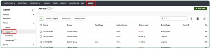
Step 3: Access the Assets Page
- Once logging in, navigate to the Assets New page under the Admin tab.
- Enter the IMEI number of the asset tracker you noted earlier in the search box.
- You will notice that the asset name appears as Azuga Devices by default, along with the Device Type assigned during initial testing.
- At the end of the asset row, click the three-dot menu and select Edit.
Step 4: Update Asset Information
- Update the form fields as needed.
- Edit or add details such as the asset name, ensuring it is a unique and descriptive friendly name (for example, Generator).
- Fill in all mandatory fields (marked with an asterisk *).
- You can add, modify, or remove text as required.
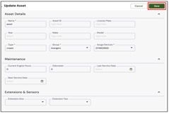
Step 5: Save the Changes
- Click Save to save your changes.
- Repeat the same steps for all remaining assets.
- Remember, each asset name must be unique; duplicate names are not allowed.
Viewing Assets Location
The Equipment Live page in the Azuga Fleet platform enables real-time tracking of your equipment, providing an up-to-date view of all items linked to the asset tracker. The Asset Tracker reports every 2 minutes when in motion and every one hour when stationary.
Key details displayed include:
- Equipment status (e.g., with or dropped from a tracker)
- Current location (address)
- Last reported location and timestamp
You can also view the equipment’s location directly on the map, based on the associated tracker. Simply pan the map to locate the tracker and its linked equipment in the live view.
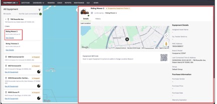
Click See Details to access additional information about the equipment, and select History to view its location history.
PDF copy of the Installation Guide - GL601MG Solar Powered Asset Tracker
For further assistance, contact customercare@azuga.com
Was this article helpful?
That’s Great!
Thank you for your feedback
Sorry! We couldn't be helpful
Thank you for your feedback
Feedback sent
We appreciate your effort and will try to fix the article